Back in the days when PCB making was expensive I started to look at ways to do that on my own. There were basically two: photo lithography and etching or milling. I did not like the idea of having to handle the nasty chemicals for etching so I first decided to get myself a CNC milling machine. Later on I found that milling had other issues so I stopped that and did invest in a small etching setup and so the CNC mill started to collect dust in a corner. This was about 2004. Now, about 14 years later, in the days of the maker movement, 3D printing and a much much better free software ecosystem to work with machines I decided to blow new life into my old CNC mill.
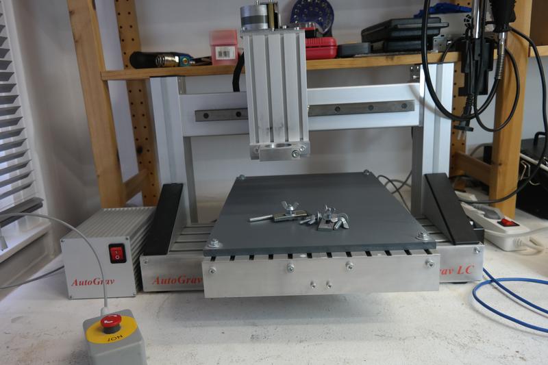
AutoGrav LC – CNC milling machine
That’s the machine! The original software drove the whole thing through a PC’s parallel port, which today no PC has anymore. And it was a set of MS-DOS programs directly accessing the PCs I/O ports, so no way to get this running on modern operating systems anymore – neither would I want to.
So first of all I needed to find out how this parallel port interface worked.
Parallel Port Interface
It turned out to be pretty straight forward. The three stepper motors (X, Y & Z) are controlled by two signals each: direction and step. The rest is handled by a stepper motor driver embedded in the machine. This makes control pretty easy! Then there are a bunch of switches – end stop switches for each axis, an emergency stop switch (the box to the front left on the photo above), a general purpose sensor and a length sensor. And there are two additional actuators, one controlling a relais for enabling the milling motor and a relais for enabling an optional cooling device (like a cooling liquid pump).
After some measuring and testing I found all of them on the parallel port:
| Parallel Port DB25 pin |
Function |
| 1 | spindle on/off |
| 2 | direction Y |
| 3 | step Y |
| 4 | direction X |
| 5 | step X |
| 6 | direction Z |
| 7 | step Z |
| 8 | – |
| 9 | – |
| 10 | end stop Y |
| 11 | end stop X |
| 12 | end stop Z |
| 13 | probe sensor |
| 14 | cooling on/off |
| 15 | stop switch |
| 16, 17 | en-/disable stepper driver |
| 18-25 | GND |
Pretty easy, isn’t it? Next question was, how do I control this from a PC?
Interface to PC
Since this has been a side project I just occasionally looked for solutions, from time to time and without much energy. It turns out that my reluctance became bliss 🙂 With the rise of the maker communities a lot of stuff has been developed for low cost machine control interfaces. So at some point I found GRBL which is exactly what I needed! It is a firmware built with the Arduino framework and runs on, you guessed it, cheap Arduino hardware!
So I got myself a cheap Arduino Uno clone from eBay and wired it to my machine:
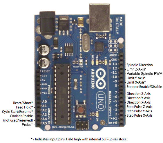
As you can see, the mapping to my machine was pretty straight forward. Flashing the board with the latest GRBL software was also pretty easy using the Arduino interface. The result is a USB device showing up as /dev/ttyUSB<n> in Linux, which behaves like a serial port and which now accepts G-Code to control my machine – awesome!
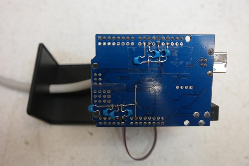
During testing I found that the inputs (for end stops and sensors) are very sensitive to all kinds of EMI, e.g. switching the relais for the milling motor (just the relais, not the motor) caused the end stops to trigger which again caused the machine to go into an alarm stop state. So I added 100nF capacitors from all switch inputs to GND which resolved that:
Control Software
The hardware part is the part that scared me so many years and it turned out to be solvable with the Arduino Uno board, some wires and a soldering iron. That part was easy. But what I do with the machine now? Or in other words, how do I control the machine from a PC? And worse, how can I draw or model something, turn that into something that the machine will understand and then how do I feed it into the controller?
First I wanted to have a software to simply manually drive the axis. After some searching I found a pretty nice graphical user interface written in Python which exactly matches my needs, it is called bCNC, from its homepage: „GRBL CNC command sender, autoleveler, g-code editor, digitizer, CAM and swiss army knife for all your CNC needs.“, here is also a link to the WiKi.
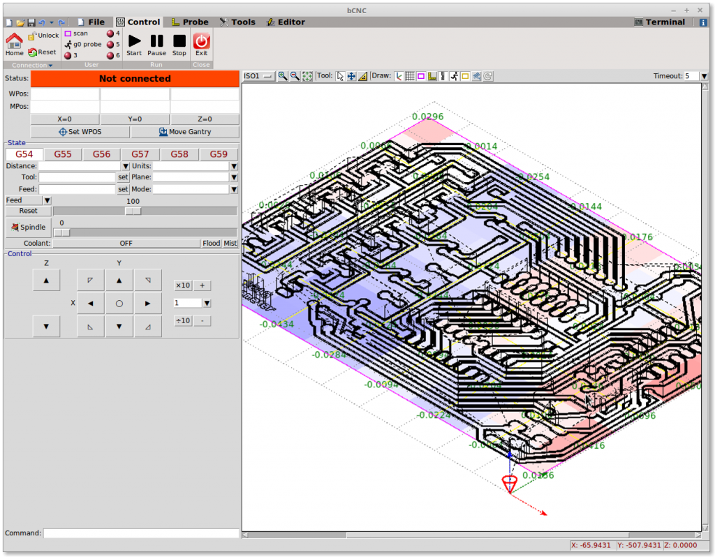
Using bCNC you can send G-Code to the controller and also do a lot more, like initializing the machine, manually driving the axis, setting of the coordinate system origin, editing of G-Code etc. It is very capable – almost too capable for my limited understanding of this kind machines. So this may be a word of warning if you want to dive into the world of CNC machine control – it is a rabbit hole! You can very quickly spend days after days figuring out your way. But it can be very rewarding! Once you figured out a workflow that fits for you and your needs you will have an automated machine at hand that will work very precisely for you.
So back to machine control, getting used to bCNC and the necessary steps to control the machine is one thing. It took me about a day to configure and setup bCNC properly and also to configure the GRBL controller – switch polarity, maximum stepper speeds, size of working area and most importantly the number of steps per mm. Driving the motor is one thing but you also need to know how far it will move with how many steps. This took me quite a while, basically trial and error measured with a caliper – the solution: 460, my machine seems to take 460 steps for 1mm of head movement (conversely the minimum movement is 1/460mm).
The next question was: Now I have a machine, a hardware controller (Arduino Uno), firmware for the hardware controller (GRBL) and software to control the controller (bCNC), how do generate G-Code from a drawing? And which drawing?
Generating G-Code
G-Code is a pretty complex thing. It does not only contain the description of the movements of the head but also a whole bunch of commands to control the machine (motors on/off, tool changes etc.) and also setting up coordinate systems etc. So when generating G-Code this has to be generated as well and with your machine and machine setup in mind. And then there are more nifty things that need to be taken into account. Imagine you want to mill out something, say a simple rectangle. But the milling drill is not indefinitely thin. If you would follow the exact path of the rectangle you would end up with an error of 1/2 of the milling drill diameter. To take this and a lot more into account there is so called CAM (Computer Aided Manufacturing) software which takes your drawing as input, applies different tool and machine parameters and outputs machine readable data that will actually drive the machine – in this case G-Code.
It seems that this CAM step is a complex thing. You can usually guess the complexity of a task on the amount of free software compared to non-free software existing. There are quite a number of non-free CAM processors to convert a diverse wealth of input, very often DXF, into machine control, often G-Code. There are also quite some free solutions but most seem very specialized, either just solving the problem of the developer or just for a very specific use case.
I am, as of today (January 7th 2019) still looking for the best solution. At the moment the seemingly most capable one I came up with is dxf2gcode (comes with Debian Linux). It has a nice GTK+ user interface. Just that up to now the GCode I generated with it does not really work with bCNC. But this could also be a matter of configuration. At least dxf2gcode runs stable (in contrast to e.g. PyCAM) and seems to offer the most important features I need.
My current workflow looked like this:
Inkscape, draw something -> export as DXF -> use dxf2gcode -> bCNC -> mill
I will hopefully update this some time soon 🙂
PS: If you happen to have the same (or similar) machine I will gladly share all my data, configs etc. with you.
oh wow, this is Amazing, we’re thinking of making our local FabLab’s CNC-Mill and -Laser in Siegen a little bit more open, i’ll definitely try some of this when the people doing the wiring are done doing the wiring 😀 is this dxf2gcode also working for 3d-ish things, like on a 3-Axis machine, generating heightmaps, exporting layers to dxf and making gcode? 🙂
Honestly, I have not tried full 3D designs with it yet, I was already very happy that my old machine started to move again and that I was able to put 2D designs on it. By now I have also removed dxf2gcode from my workflow again since bCNC can do the same thing and much more, once you figured it out 🙂 There are nifty details like having to mill deeper cut outs in several layers in order not to break the cutter. All of this can be handled on bCNC – but it takes a lot of experience and time. On the other hand you have to do it or you will quickly ruin your tools and especially cutters.
Let me know when you have your machine wired and I can come over and we can play with the software together – it is just 15min by foot from my office 🙂
Hallo Nicole,
sehr schoener Artikel, wie Du die alte CNC-Fraese mit freier Software zum Laufen gebracht hast. Ein Kumpel und ich tragen uns mit dem Gedanken, auch mal so eine CNC-Fraese zu bauen und zu betreiben. Derzeit sind wir aber noch aus Zeit- und Raummangel bei der Idee und nicht weitergekommen.
Unser Ausgangspunkt war das github-Repo hier:
https://github.com/bcndynamics/MaduixaCNC
Wir wollten aber von Holz zu Alu gehen und den Werkzeughalter vielleicht nochmal neu konstruieren. Allerdings haben wir auch ein bissel Angst vor der Elektronik und wie Dein Artikel zeigt, ist das selbst bei ausentwickelten Maschinen nicht zu unterschaetzen.
Gibt es das Modell Deiner Fraese noch zu kaufen? Wie hoch sind etwa die Kosten?
Warum ich auch geschrieben habe: Ich hab ein bisschen an FreeCAD mitgearbeitet und nachdem was ich weiss, gibt es dort eine recht umfangreiche CNC-Fraes-Workbench, die einem allerhand zur Erzeugung von G-Code abnimmt. Insbesondere werden die Toolkorrekturen schon gerechnet und man kann sich den Werkzeugpfad vorher anschauen. Vielleicht ist das ja was, um Deinen Workflow ein bisschen zu vereinfachen.
Viele Gruesze
Johannes
Dear Nicole,
I am not sure, why my last comment was not published. Maybe I blocked too much with my uMatrix 🙂 That’s a great article on how to reactivate your old CNC mill. A friend of mine and I, we wanted to build a CNC machine ourselves from scratch, but due to time constraints and the necessity of a workspace before, it stays only an idea so far. We wanted to derive it from:
https://github.com/bcndynamics/MaduixaCNC
But instead of wood, we’d like to use aluminum and maybe the tool holder could be improved. We have also some fears of the electronics, and like your article told us, it is not trivial to bring it online with pure free open source software.
Is it still possible to buy your baseline CNC machine somewhere? What was the price? What is the accuracy?
Maybe in the future we have the time to revive the project again, but as I said, so far only ideas 🙂
Why I wrote: I’ve worked a bit on FreeCAD https://freecadweb.org/ in the last couple of years, in particular on the FEM part there. But as far as I remember, they have a quite good G-code workbenched named ‚Path‘ where you could easily generate G-codes for 3D parts. And since you can import drawings also into FreeCAD, maybe this could improve your workflow a bit. I know that this workbench is also able to administrate several tools and the G-codes are calculated with tool radius corrections already. What I don’t know: Whether the workbench is able to define a user defined header to proper initialize exactly your machine for cutting.
Hope this helps.
Keep up your good work!
Best regards
Johannes
Sorry for the ‚delay‘!
No offense, I actually appreciate it very much, I just did not have the time yet to look into it, I am super busy right now with my job at Purism.
I would not recommend looking for my specific machine. If you want to build something on your own you can get proper parts very easily form eBay or other sources. If the machine does not need to be very big, to get stepper motors and controller from eBay which are sold as kits for 3D printers. There are plenty GRBL/Marlin controller boards which include everything you need – stepper drivers, controller and even a display. I got one set of such stuff once to build another XYZ machine and it cots me, including steppers, less than 100EUR. The aluminum parts to build a frame etc. are also easy to source, e.g. from Dold Mechatronic GmbH – but not so cheaply. You will want to look for aluminum profiles, nut stones, corner connectors and most importantly linear bearings. For a mill I would recommend threads for driving the moving parts – slower but more precise and can convey more force. For the spindle itself you can also find good brushless high speed spindles on eBay.
The whole kit should be a little than 1000EUR in the end – which is still less than what I paid more than 15 years ago for the machine I have.
I recently tried FreeCAD to construct a bit more complex part – a prototype case design for the Purism Librem 5 phone PCBs. I was new to FreeCAD and maybe I took some wrong turns and that’s why I failed. Anyway, I had to create a part with many holes in it. I used the difference tool, create a new part with the hole shape and then the difference to the main body. This worked out well but the more holes I created the deeper the ‚tree‘ of the main part became until the point where FreeCAD choked on it and I was not able to do anything anymore, it would just crash. Pretty frustrating. What worked instead was to unify all that into a single body (i.e flatten the tree) but then of course you loose the ability to edit the cut outs – once flattened/unified it is just one single thing and I did not find any means in FreeCAD to edit this again (maybe there is but too hidden for me). So I gave up on FreeCAD for now and went back to OpenSCAD for that piece.